BACK TO LISTING
Tom Thumb
Installing a Tiller Pilot on my Frances 26
I often sail my Frances26, Tom Thumb, solo and wanted to install a tiller pilot. I purchased a Raymarine ST1000+ then found it difficult to install as her canoe stern was not wide enough for transverse mounting as described in the installation manual. Enquiries with Raymarine and others only resulted in a suggestion for a bracket on the rudder post at right angles to the tiller with the unit hanging outside the boat. I didn't want to do this for reasons of ease of use, safety and aesthetics.
I came up with my own design which mounts the unit internally of stern rails using a length of main sheet traveler track and car, 4 blocks and some Dyneema line. I have now completed the installation. It works very well and I am thrilled. But there were a few tricks to installing it so I have documented these in the hope of assisting others wanting to install a tiller pilot. Here are some details:
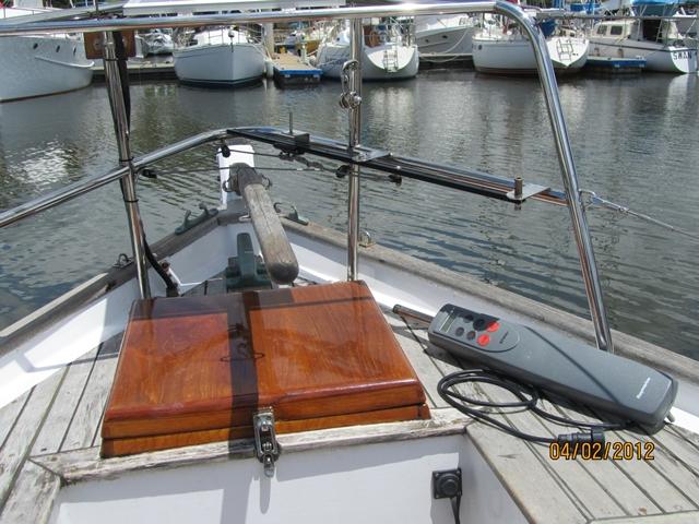
Photo 1
This shows the overall layout:
- A main sheet traveler track is mounted on the stern rails with 3 tabs – 2 visible and a smaller one inserted into the aft end of the track
- The tiller pin is mounted onto a traveler car which runs up and down the track
- 2 Dyneema lines are used to connect the traveler car to the tiller using 4 blocks:
- One either side of the tiller at the recommended distance from the rudder axis (18 inches for the ST1000)
- One at the stern for the starboard line
- One on the port side ahead of the port block connected to the tiller
- A power outlet on the port side rear of the cockpit well
- A large snap shackle to hold the pushrod away from the track/traveler when not in use
- All custom work is in 316 stainless
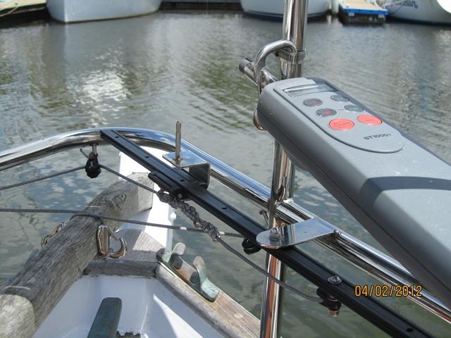
Photo 2
- The snap shackle works very well – I remove the pushrod from the tiller pin and push it through the gate of the snap shackle in one easy motion. The other end of the unit remains in its mounting socket while this is done so only one end of the tiller pilot is free. Make sure the snap shackle is still big enough to accept the pushrod taking into account the mounting of the snap shackle
- Originally I had a ring welded to the riser on the stern rail but this was much more cumbersome to use:
- remove the pushrod from the tiller pin
- Remove the other end of the tiller pilot from its mounting socket
- Insert the pushrod into the ring
- Re-insert the other end of the tiller pilot into its mounting socket
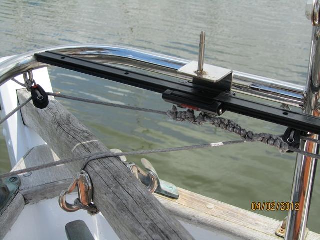
Photo 3
- I used a Ronstan Series 19 ball bearing car and traveler because I thought there would be some twisting forces on the traveler car. But I had a piece of 316 SS bent up to hold the tiller pin on the opposite side of the car to the shackle. All forces are in line and there don’t seem to be any twisting forces so I probably could have used the cheaper I-Beam system. I mounted them upside down so that I could tie the lines to the shackle more easily. In retrospect I don’t think I needed to do this and it has exposed the ball bearings to the weather and they get a little sticky requiring occasional lubrication.
- I fitted 316 spring hooks to the tiller and wrapped the Dyneema line around the tiller. This allows the tiller its full scope of movement, with the tiller passing underneath the blocks when hard over
- There is enough slack in the lines, when the tiller is amidships, to allow the lines to be easily unhooked
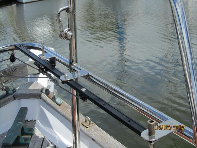
Photo 4
Laying it all out was the hard bit:
- My original intention was to only connect the Dyneema lines when I intended to use the tiller pilot. But given that the units works so well and is so easy to use I leave it connected all the time and the traveler car moves backwards and forwards on the track as the tiller is pushed/pulled, whether I am using the tiller pilot or not.
- The pushrod on the ST1000 moves in and out 10 inches but at the prescribed fixing point, 18 inches from the rudder axis, the full scope of tiller movement is well in excess of 10 inches and you will want every bit of available range for maneuvering in tight spaces
- For my boat:
- With the tiller hard to port the traveler car is at the rear of the track. Note that this is further back than the pushrod will push the traveler when the tiller pilot is in use
- With the tiller hard to starboard the traveler car is as far forward as it will ever be. Note again that this is further forward than the pushrod will push the traveler car when the tiller pilot is in use AND ALSO that the traveler car will be further forward than the port tiller block. This is the reason for the fourth block. The tab supporting the middle of the track must also be far enough forward to allow the traveler car its full forward movement
- With the Dyneema lines tight when the tiller is pushed hard over there is a little slack with the tiller amidships (about an inch) I thought this might be a problem in use but the unit doesn’t seem to have a problem with this, it just keeps on correcting bit by bit until it gets the course correction it wants
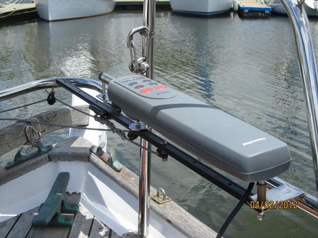
Photo 5
Here is the Raymarine ST1000+ mounted
and ready for use. Overall it meets all my objectives:
- It is mounted inboard making it
easy and safe to use. I don’t have to hang over the side/back of
the boat to mount it or take it down and all controls are easy to
see and use
- The unusual angle of the unit with
respect to the direction of travel was no problem. The alignment of
the compass was carried out with the standard setting up process
- This wasn’t a trivial exercise
though. I put in a good deal of time in design, procurement and
project management. I even removed the stern rails to take them to a
fabrication shop. All up costs for materials and 3rd party labour (welding and marine electrician) was between 150% and
200% of the cost of the tiller pilot
- I make a habit of plugging in the
tiller pilot and mounting it in its standby position in the snap
shackle whenever I go out so that there is no reason not to use it.
And I find it very handy at times